Lockdown project: Making a gamepad
Why would I make a gamepad? Here is the short version:
The following guide might seem like a lot of work, and I suppose it is. Having said that, what I'll end up with (with any luck), is a universal gamepad I can plug into any system that has a USB port. This will be independent of needing any drivers and won't depend on a specific operating system.
... and here's the long version:
Most gamepads are not completely cross-platform. You need different drivers for Mac, Windows, and Linux. Also, these drivers need configuring differently. (Not what you want to struggle with when you just want to plug in a controller and play)
Here's an example of what I mean. On Mac OS X, there's a utility that changes the buttons pressed on a gamepad into keyboard presses. (Called 'Enjoyable') Essentially it's taking the signals sent by the gamepad, reinterpreting them in software, and changing them to mimic keyboard keys being pressed:
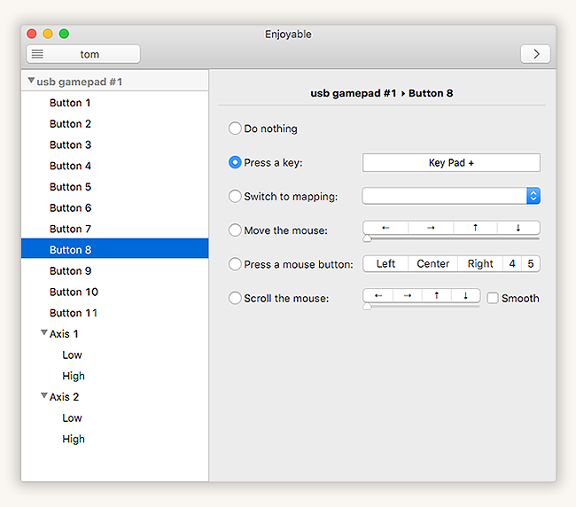
Now, this is fine and works for Mac OS X. There's also 'XPadder' for Windows (not free)
At the time of writing this, I can't find anything with a graphical user interface that does this on Linux.
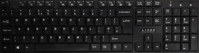
Which got me thinking... what is the most universal device that can understand key presses? That's right - a keyboard. A keyboard works on everything you plug it into. It doesn't need extra drivers or configuring in a special way. It just works (to coin a phrase).
The other nice thing about this approach is it cuts out any delay between these keys being interpreted via software. As it's still seen as a keyboard according to the computer. Plus, you can attach as many keyboards as you like to the computer and they will just function regardless.
Happily enough, I have plenty of old keyboards laying around. Taking one apart, I discovered this circuit board:
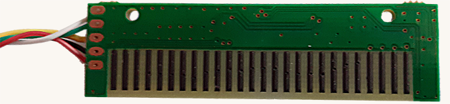
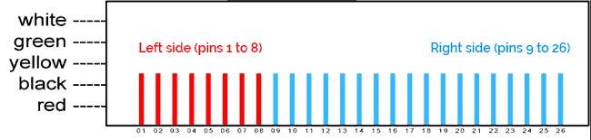
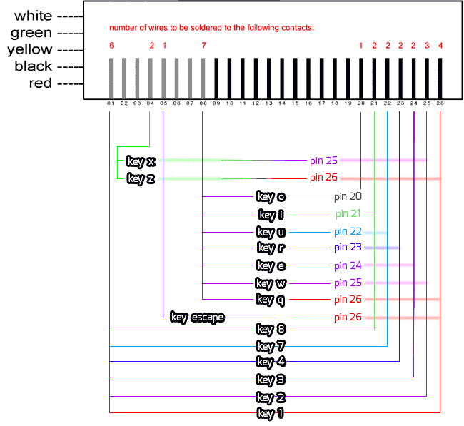
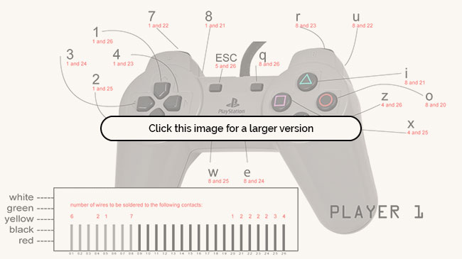
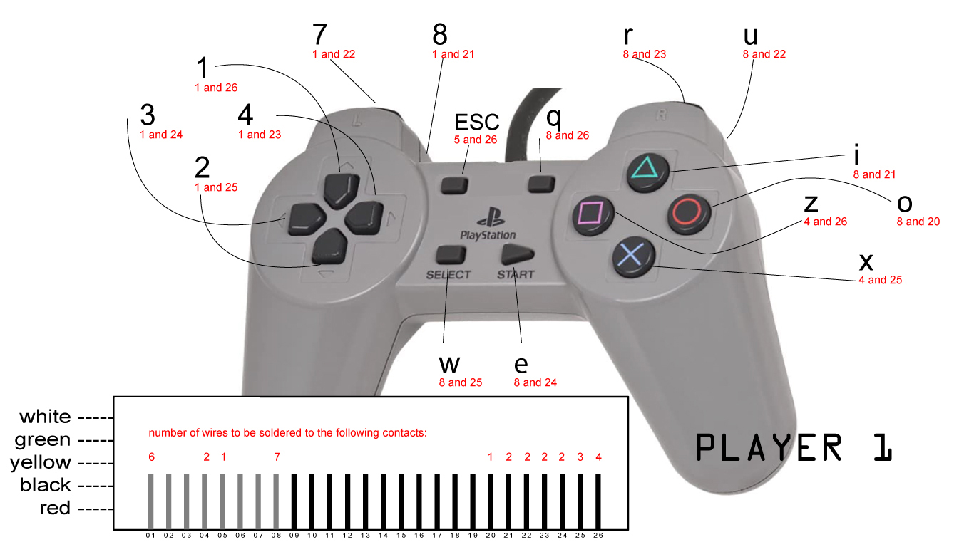
The first step was to count how many pins this board has. (26). I then traced with a pen the inputs from the keyboard mechanism back to the board. It turns out, the first 8 pins on the left-side of the board are used for one side of the circuit. The other 18 pins are used to map to different keys.
Knowing this, I could essentially mimic any key press by joining two sets of wires together. Then came the task of figuring out what should join to where to activate the keys I want:
This looks a lot more complicated than it actually is.
It's pretty much, pins across from the left: 1,4,5 and 8 are what you need wires coming off of. Then, from the right-side - starting with pin 26 - I started mapping which wires did what.
I hope this makes sense, but to simplify it, here's a easier to read version.
join pin 01 to pin 25 to mimic the '2' key.
join pin 01 to pin 24 to mimic the '3' key.
join pin 01 to pin 23 to mimic the '4' key.
join pin 01 to pin 22 to mimic the '7' key.
join pin 01 to pin 21 to mimic the '8' key.
join pin 04 to pin 26 to mimic the 'z' key.
join pin 04 to pin 25 to mimic the 'x' key.
join pin 05 to pin 26 to mimic the 'escape' key.
join pin 08 to pin 26 to mimic the 'q' key.
join pin 08 to pin 25 to mimic the 'w' key.
join pin 08 to pin 24 to mimic the 'e' key.
join pin 08 to pin 23 to mimic the 'r' key.
join pin 08 to pin 22 to mimic the 'u' key.
join pin 08 to pin 21 to mimic the 'i' key.
join pin 08 to pin 20 to mimic the 'o' key.
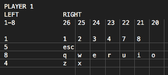
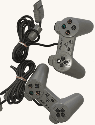
I started off counting how many buttons I wanted on my controller. For me (and this is personal preference), I always found one of the most comfortable controllers to hold and use was the Playstation ones. I'm specifically talking Playstation 1 and 2. Playstation 1 controllers are really cheap to get hold of on eBay - £4.80 including free delivery for two Playstation 1 controllers.
Having counted that the standard Playstation controller has 14 buttons, I wanted two extra. One for exiting out of the game (escape key) and another I could map as a spare. (some arcade games I may run on an emulator need a button to trigger the 'insert coin' function) - so on this screenshot, you'll see I have photoshopped two extras above the normal 'start' and 'select' buttons:
So, this means that I had to solder wires onto the PCB (not an easy task, and probably the most fiddly bit up to this point). This is what that looks like in practice:
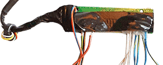
Yes, it's a bit messy, but it works. I've just got to purchase some little switch buttons now and wait for my controllers to arrive.
The new buttons are little press switches, and are 6mm square. They can be wired directly into the 'keyboard' PCB that I plan to try and fit into the controller (somehow).
Here are the bargain Playstation 1 controllers which arrived today. Apparently they are in working order. Seems a shame to take them apart, however they were so cheap, I couldn't have made them any cheaper for what I paid for a pair of them.
The switches have also arrived too. (25 push switches for 85p from eBay.) These switches are only 6mm square and will hopefully be ideal for underneath the Playstation 1 buttons.
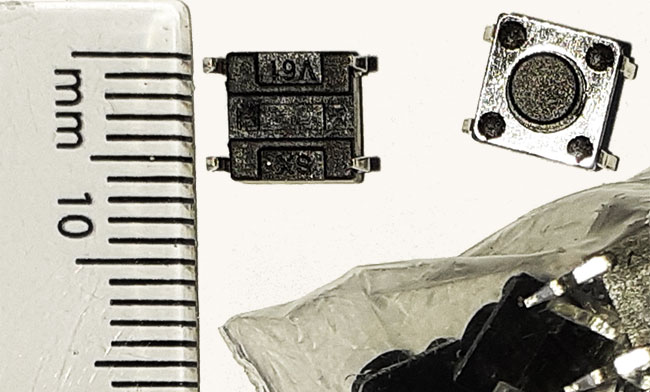
I now need to solder all my wires as shown in the diagrams above, to 16 switches (32 connections to be made).
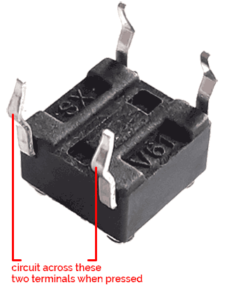
I wanted to be sure I knew which terminals activate the switch. All I actually needed are two terminals, even though these come with 4.
To test these switches out, I wired up a 1.5v battery with a bulb. I then connected the switch on the two terminals shown until I found which one completes the circuit when the button is pressed.
So now I know how I'm going to wire my switches (soldering to any terminal marked 'SX', and the corresponding one on the side marked 'V61'), this will be my next job. After that, I'll need to make some kind of switch holder so that these can be positioned underneath the original Playstation 1 controller buttons.
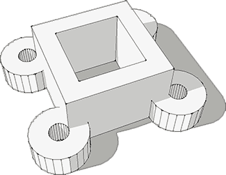
Here is the first go at my switch holder. It's 3D Printed, and you can download the model here.
It holds the switch in place but I wanted the height to be adjustable so I can fine-tune the button click. To make these holders adjustable height-wise, I have put small screws on each corner. The idea is I can wind these up and down so I can get the feel of the button click exactly how I want.
After a bit of test-fitting, I've realised because the directional controls are so close together, I wouldn't have been able to fit my button holders where I needed them. There wouldn't have been enough room. So, this has led to a redesign of the button holders.
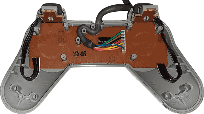
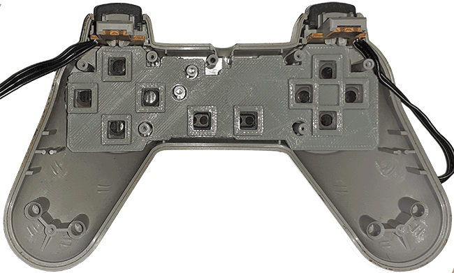
This is the inside of the Playstation 1 controller, and as I mention, it's led me to a bit of a rethink. I'll keep the shoulder buttons at the top where they are and use the existing black wires to join to my new circuit board.
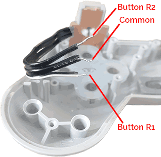
The wiring for these shoulder buttons are as follows. The middle wire is the common wire. The top wire is button '2' (Shoulder button L2 or R2), and the bottom wire is '1' (Shoulder button L1 or R1).
So, thinking about how I'm wiring my new board in, I'd connect the wire from termial 8 on the board to the common wire. Then I'd connect the wire from terminal 23 on the board to the bottom wire on this diagram (the R1 button). I'd connect the wire from terminal 22 on the board to the top wire on this diagram (the R2 button).
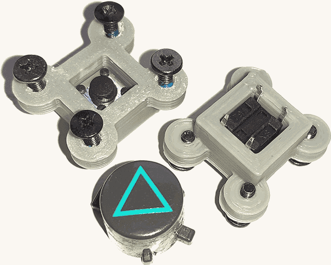
The brown circuit board can come out as I won't be using it. However, I will need to copy the shape of this circuit board, so I've produced a new model:
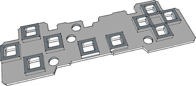
I've also built the button holders into this new plate at the same time which should make life easier. You can download this new revised model here for 3D printing.
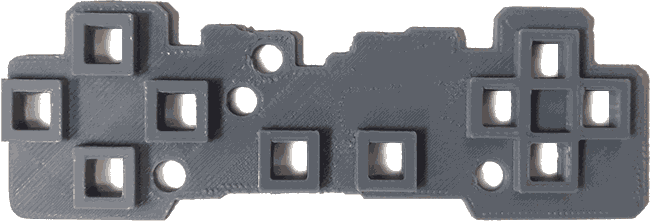
Here is the new 3D Printed board.
... and here is the new plate inside the controller. I've just got to wire my buttons in now, which is the next job.
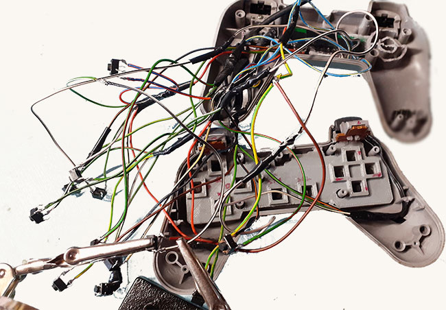
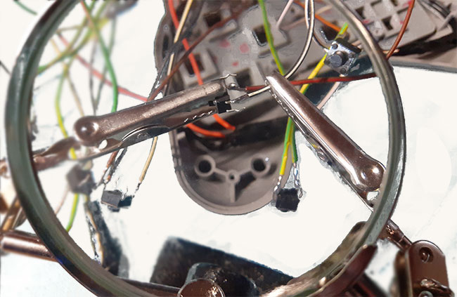
Joining the wires to the switches is really fiddly. I bought myself a tool with two clamping arms and a magnifying glass. It holds the wires in place while soldering and made the process so much easier. For £5 it's well worth it. (It's no fun getting old!)
I just hope they somehow all fit inside now. It's going to be a squeeze...
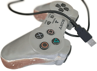
Getting this to all fit together again was a huge pain. So much so, that I couldn't actually close up the gamepad completely. I'd be left with a gap at the bottom edge.
There were just too many wires, so I filled the join with fibreglass and sanded it smooth with fine sandpaper.
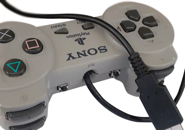
It's finally all done, and all the buttons work as they should. I've got my two extra buttons at the top of the pad. I decided to put them near the shoulder buttons as the space inside the pad lends itself to that instead of being above the select and start buttons.
So far, I've tested it on Windows, MacOS and Linux and it works fine. Just for a laugh, it is even compatible with my old Mac OS 8.6 classic mac. I'm pretty sure it will work on anything.
Back to Forum Listing